After working more on my voxel game using the Runtime Mesh Component to generate meshes, I ran into some issues with it and here I want to document them as well as offer solutions.
A lot of these issues stem from the fact that I don’t particular work with graphics or 3d modeling so a lot of these things elude me when I first started creating procedural meshes. None of the guides/tutorials on using either the runtime mesh component or the built in procedural mesh component go over them heavily either.
Normals, Tangents, UVs
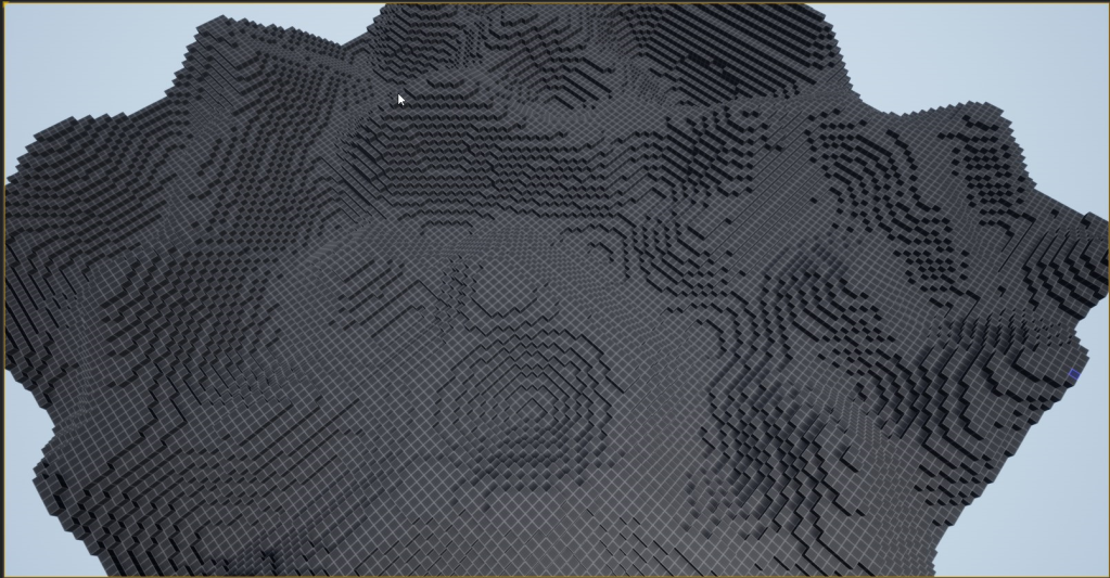
So After I managed to generate my meshes and add materials onto them I started to notice something, my boxes looked flat. Granted they are cubes and thereby has flat surfaces on all sides, they still looked flatter then then they should. I pulled up the default UE4 cube and put the same material on it and compared the cube faces next to each other and mine was flatter than the default cubes.
UVs
First I decided to check out my UVs. After a lot of looking stuff up, I realized that it was because my UVs are wrong and I didn’t really set my normals and tangents. If you were following my last post on the Runtime Mesh Component, the UVs are stored in EmptyTexCoords variables. The index of the UV vertex is the same index as what we put in for the vertex coordinates, so if you add a vertex to the vertex array you should add a UV/normal/tangent value into their respective array as well.
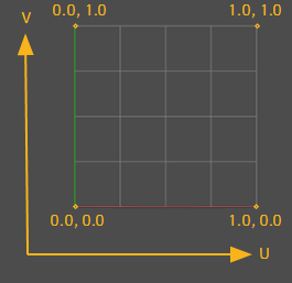
For UVs if you looked it up on Google, you will know that UVs starts at the bottom left origin and increases up/right.
So I went back into my code and fixed them for one side and this is what I got. and I also threw on a UV tester texture on my material to see it.
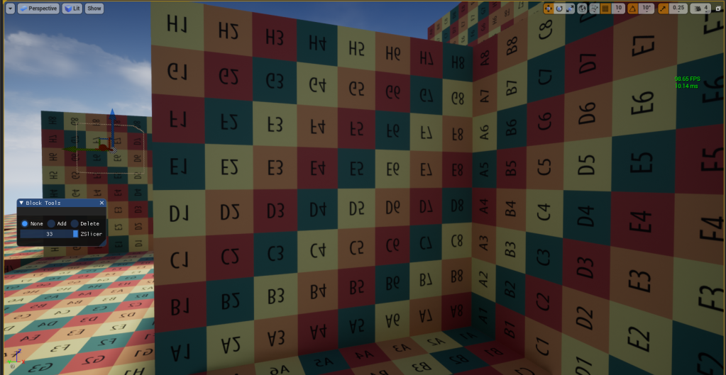
The UVs are backwards and upsidedown! What gives. Well after more searching it turns out that Unreal Engine has the UV origin on the top left and grows to the bottom/right.

After fixing it to match those UV coordinates, it worked!

Normals
Alright the normals are pretty straight forward, espcially since my mesh is basically a bunch of cube faces that are world aligned, so their normals are either 1 or -1 on the axis they are facing. A normal is just the normalized vector that comes straight out of a mesh.
If you open the default cube that comes with UE4 at /Engine/BasicShapes/Cube.Cube and check the top for normals. Since each corner vertex is actually 3 vertexes (1 for each face), the best way to check for the normal is just the one in the middle of each face. The direction that it comes out is the normal for that face. So for example, the normal for the top face is coming up so it would be FVector(0.0f, 0.0f, 1.0f)

You can also drag the default cube into the world and turn on world normals visualizer to check if they match. Each normal direction would have its own color.

Tangents
I orginally ignored this one because I didn’t really know what it does and it was really hard to find anything about this, but apparantly the engine uses both normals and tangents to draw/color/texture the meshes and if you don’t have tangents (or the correct ones) some faces won’t get displayed right.
For me when I realized something is wrong is when some of the faces in the world normal visualization doesn’t have the normal bumps like above. If you are using a material with a normal map and you turn on that visualization you should be able to see the normal map on the faces, if it is flat then it’s not set up correctly.
I’m not exactly sure how tangents are calculated from just one normal. I just looked at the default cube and go from there

For example, the tangent for the top face here is FVector(1.0f, 0.0f, 0.0f). And I just add them in to my mesh generation code.
After everything is fixed, the blocks in the world looked right finally. You can see the “bump” for the normal as well as the other properties of the material.

The Remaining Parameters
I’ll just briefly go over the other parameters that I missed and/or glossed over since I’m not really using them right now.
StaticProvider->CreateSectionFromComponents(0, 0, 0, Positions, Triangles, EmptyNormals, EmptyTexCoords, Colors, EmptyTangents, ERuntimeMeshUpdateFrequency::Average, true);
The above is the call to draw the mesh, the parameters are as follows:
- LODIndex: This is the 0 indexed value for LOD, since I have no LOD meshes, my mesh is always on the 0th index
- SectionIndex: This is for creating mesh sections, it is used if you want to apply different materials to a giant mesh, you will make sections for each material. I will use these values later when I implement other block types. The downside of using it this way is that you can’t really do greedy meshing. That’s a optimization step that I’ll work on later if it is needed. There are other ways to implement material/texture that doesn’t rely on the section index (use the UV coordinates instead for example) but they are usually a lot more cumbersome to use especially since UE4 has such a powerful material system.
- Vertices: The list of locations for each vertex.
- Triangles: The list of triangles in the mesh, each triangle is a set of 3 points, listed as 3 indexes of the vertex array.
- Normals: List of normals for each vertex
- UV0: There are actually a few sets of UVs (UV0, UV1, UV2, UV3). They are optional and are the UV coordinate of each vertex. Extra UVs layers can be used to from pretty cool effect from what I hear but it is way over my head.
- Vertex Colors: This is list of color of each vertex. If no normals are given then the color of each face is the average of the vertices of the triangle at the point in the triangle. If you are using UVs you can store extra data in the vertex colors that can be queried in the material.
- Tangents: List of tangents for each vertex.
- UpdateFrequency: I haven’t really played with this but this simply tells the Runtime Mesh Component how often the mesh will be updated during runtime and there are what I assume some optimizations behind the scenes depending on what option you choose. The options are: Average, Frequent, Infrequent.
- CreateCollision: This creates collision for the mesh. If you are rolling your own collisions, turn this off.
Conclusion
So yea, I think that above covers it. There were a lot more gotchas that I thought from someone that is not from the games/graphics/3d industry. I might do a part 3 if I encounter other issues down the line.

